When precision matters in land surveying, construction layout, or geospatial data collection, the theodolite stands as one of the most trusted optical and electronic instruments in the field. Unlike simple angle-measuring devices, a theodolite is engineered to deliver repeatable, high-accuracy angular measurements across both horizontal and vertical planes. Understanding how this instrument achieves such precision helps engineers, surveyors, and project managers make informed decisions about their measurement workflows and equipment choices.
The accuracy of a theodolite does not come from any single feature but rather from a carefully integrated system of mechanical, optical, and electronic components working in harmony. From the leveling base and the graduated circles to the reading systems and the line of sight, every element contributes to the instrument's ability to capture angles with minimal error. This article explores the internal mechanisms, operational principles, and best practices that enable a theodolite to measure angles accurately in real-world surveying conditions.
The Core Architecture of a Theodolite
Horizontal and Vertical Circles
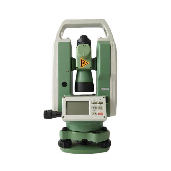
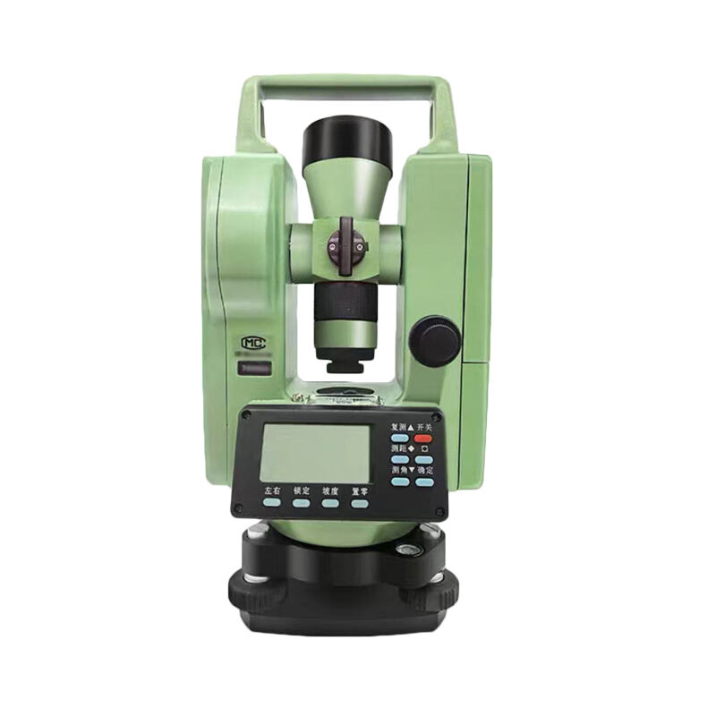
At the heart of every theodolite are two precisely graduated circles: the horizontal circle and the vertical circle. The horizontal circle rotates around the vertical axis of the instrument, allowing the operator to measure horizontal angles between two points. The vertical circle is fixed to the telescope and rotates around the horizontal axis, enabling accurate measurement of elevation or depression angles. Together, these two circles provide the angular data that defines the spatial relationship between any two observed targets.
In a modern electronic theodolite, these circles are encoded with fine angular graduations that can be read by photoelectric sensors. The density and precision of these graduations directly determine the minimum readable angle, commonly expressed in arc-seconds. High-performance instruments can achieve reading resolutions of one arc-second or finer, which is essential for tasks such as control point surveying, tunnel alignment, or structural monitoring where even minor angular deviations can compound into significant positional errors over long distances.
Traditional optical theodolites rely on glass circles with etched graduations, which are read using a microscope eyepiece built into the instrument. While still effective for many applications, the manual reading process introduces a degree of human error that electronic systems eliminate by automating the reading and display of angle values.
The Telescope and Line of Sight
The telescope of a theodolite is not merely a viewing tool — it defines the instrument's line of sight, which must be perfectly perpendicular to the horizontal axis and precisely aligned with the optical axis of the instrument. Any deviation in this alignment, known as collimation error, will introduce consistent angular errors into every measurement. Quality theodolite manufacturers rigorously calibrate and test this alignment before instruments leave the factory, and operators are advised to check collimation in the field regularly.
Most theodolite telescopes include internal focusing systems and cross-hair reticles that allow the operator to place the line of sight exactly on a target. The magnification power of the telescope, typically ranging from 26x to 40x in professional instruments, enables precise target acquisition even at long distances. A sharper, more stable line of sight means the operator can bisect the target more accurately, which directly reduces angular reading error.
How Angle Measurement Works in Practice
Setting Up and Leveling the Instrument
Accurate angle measurement with a theodolite begins before any angle is even read. The instrument must be correctly centered over a ground control point using a plumb bob or optical plummet, and then leveled so that its vertical axis aligns with the direction of gravity. This leveling process is accomplished using a tribrach with leveling screws and a plate bubble or electronic tilt sensor. If the theodolite is not properly leveled, the horizontal circle will be tilted relative to the true horizontal plane, introducing angular errors that cannot be corrected in post-processing.
Modern digital theodolites often include a dual-axis compensator, a device that automatically detects residual tilt in both the longitudinal and transverse directions and applies corrections to the displayed angle values. This feature is particularly valuable when working on uneven terrain or when time constraints make repeated leveling impractical. The compensator effectively extends the usable leveling tolerance of the instrument while maintaining measurement integrity.
A properly set up theodolite forms the foundation for every subsequent measurement. Rushing through this step or accepting marginal leveling conditions is one of the most common sources of angular error in the field, and no amount of sophisticated optics or electronics can compensate for a poorly centered or tilted instrument.
Reading Angles with Electronic Encoders
In electronic theodolites, the graduated circles are read by absolute or incremental encoders that convert the angular position of each circle into a digital value displayed on the instrument's screen. Absolute encoders assign a unique digital code to every position on the circle, meaning the instrument always knows its angular orientation even after being powered off and restarted. Incremental encoders count graduations from a reference position, which requires initialization each time the instrument is powered on.
The resolution and repeatability of the encoder system largely determine the angular accuracy of the theodolite. High-quality encoder systems use fine optical gratings with thousands of divisions per revolution, and the reading process often includes interpolation algorithms that further subdivide the grating intervals to achieve sub-arc-second resolution. The result is a highly repeatable digital readout that eliminates the parallax and estimation errors associated with manual circle reading.
This digital reading capability also enables the theodolite to store, transmit, and integrate angle data with other survey instruments or data collectors, making electronic theodolites indispensable in modern total station workflows and robotic survey systems.
Sources of Angular Error and How They Are Managed
Instrumental Errors and Their Correction
Every theodolite is subject to a set of systematic instrumental errors that, if left uncorrected, will bias angle measurements. The most common are: collimation error (the line of sight not being perpendicular to the horizontal axis), horizontal axis error (the horizontal axis not being perpendicular to the vertical axis), and vertical index error (the zero reading of the vertical circle not corresponding to the true vertical). Each of these errors introduces a predictable offset into the measured angles.
Surveyors traditionally manage these errors by observing in both face-left and face-right positions — also called direct and reverse positions — and averaging the two sets of readings. Because most instrumental errors reverse in sign between the two face positions, the average of a face-left and face-right reading cancels the error. This technique, known as double-face observation, is a fundamental practice in precise theodolite work and is still used even when working with modern electronic instruments.
Electronic theodolites with built-in calibration routines can detect and store corrections for collimation, tilt, and vertical index errors, applying them automatically to every measurement. This reduces the burden on the operator while maintaining high measurement quality, especially in time-sensitive applications where double-face observations are not always feasible.
Environmental and Operator-Induced Errors
Beyond the instrument itself, environmental conditions can significantly affect theodolite accuracy. Heat shimmer and atmospheric refraction cause the line of sight to bend slightly, particularly over hot surfaces or long sighting distances. This effect, known as lateral refraction or vertical refraction depending on its direction, can introduce angular errors that are difficult to detect and correct. Experienced surveyors minimize this by choosing observation times when atmospheric conditions are stable, typically early morning or overcast conditions, and by limiting sighting distances where possible.
Wind-induced vibration can cause the theodolite to move slightly between the moment of sighting and the moment of reading, introducing random errors that increase with wind speed and instrument instability. Using a heavy-duty tripod with secure leg locks and avoiding observations during strong gusts helps manage this risk. In some industrial applications, the theodolite may be mounted on a fixed pillar or platform to eliminate tripod-related movement entirely.
Operator skill also plays a significant role in angle accuracy. Precise bisection of targets, consistent eye relief when looking through the telescope eyepiece, and careful handling of the slow-motion screws all contribute to reducing random errors. Training and practice are irreplaceable components of achieving the full accuracy potential of any theodolite.
Advanced Features That Enhance Theodolite Accuracy
Servo and Motorized Systems
Modern theodolite instruments increasingly incorporate servo-driven or motorized rotation systems that allow the telescope to be driven to a programmed direction with high angular precision. This capability is essential in automated and robotic surveying, where the instrument must repeatedly return to known directions or track moving targets without operator input. Motorized theodolite systems can achieve pointing repeatability of a few arc-seconds, far exceeding what is typically achievable through manual operation.
In construction stakeout and machine guidance applications, motorized theodolite instruments work in combination with prism targets and control software to automate the positioning process. The instrument continuously measures angles to the prism, calculates the prism's position relative to the design model, and guides the operator or machine to the correct location. This integration of precise angular measurement with real-time computation dramatically increases both the speed and accuracy of field operations.
Digital Communication and Data Integration
A critical enabler of modern theodolite accuracy is the ability to transfer angle data directly to external devices without manual transcription. Bluetooth, USB, and serial communication interfaces allow the theodolite to stream angle and distance data to data collectors, tablets, or survey software in real time. This eliminates booking errors, where manually recorded angle values are misread or incorrectly entered, which is a surprisingly common source of error in traditional surveying workflows.
When angle data flows directly from the theodolite into a survey computation engine, the software can immediately flag inconsistencies, compute adjusted coordinates, and generate quality control reports. This closed-loop data management approach ensures that angular errors are identified and resolved in the field rather than discovered later in the office, saving time and reducing rework costs significantly.
FAQ
What is the typical angular accuracy of a professional theodolite?
Professional-grade theodolite instruments commonly offer angular accuracies in the range of 1 to 5 arc-seconds for standard surveying tasks. High-precision instruments used in geodetic control surveys or structural monitoring can achieve sub-arc-second accuracy when used with proper observing techniques such as multiple face observations and atmospheric compensation.
How does a theodolite differ from a total station?
A theodolite measures horizontal and vertical angles only, while a total station integrates an electronic distance measuring (EDM) unit to also measure slope distances. Essentially, a total station is a theodolite with distance measurement capability added. For workflows that only require angle data, a standalone theodolite is lighter, simpler, and often more cost-effective than a full total station setup.
Why is leveling so important for theodolite accuracy?
The theodolite measures angles relative to its own vertical and horizontal axes. If these axes are not aligned with the true vertical and horizontal planes of the Earth, all measured angles will contain a systematic tilt error. Even a small leveling error of a few arc-minutes can translate into several millimeters of positional error at distances of hundreds of meters, which is unacceptable in precision surveying work.
Can a theodolite be used indoors or in industrial settings?
Yes, a theodolite is well suited to indoor and industrial measurement tasks such as machinery alignment, structural inspection, tunnel monitoring, and large-scale manufacturing quality control. In these environments, the theodolite is often mounted on rigid stands or pillars to minimize vibration effects, and targets are typically retroreflective prisms or precision-machined tooling balls rather than conventional surveying staffs.